Wireframes
-
So, I have this problem over at FW:ToW that I cannot put my finger on and I was hoping someone with more knowledge in the area of wireframes could lead me to the solution.
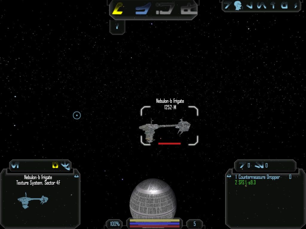
Basically, I made all of the 104 ships of FW:ToW have wireframes. They all work great, as solar objects. See below

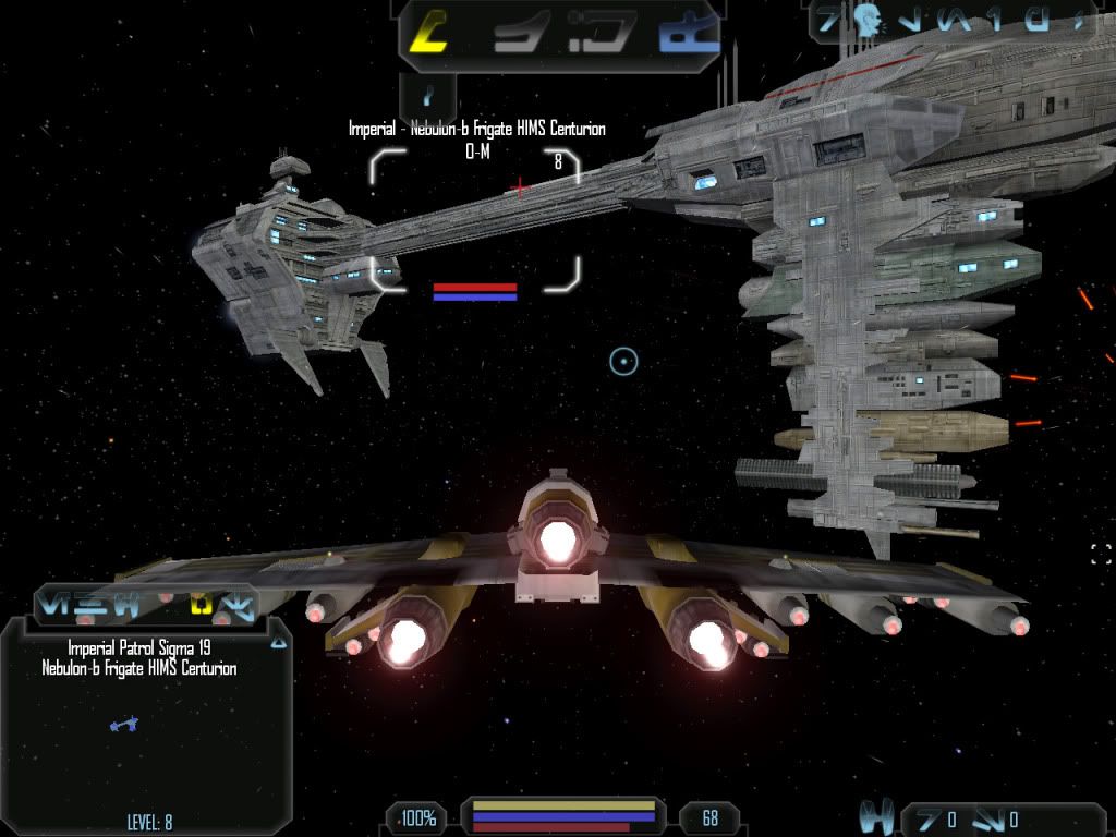
Now the main problem is that the capital class craft as NPC and player flyable ships, the ones with the largest wireframes become incredibly small. See below:

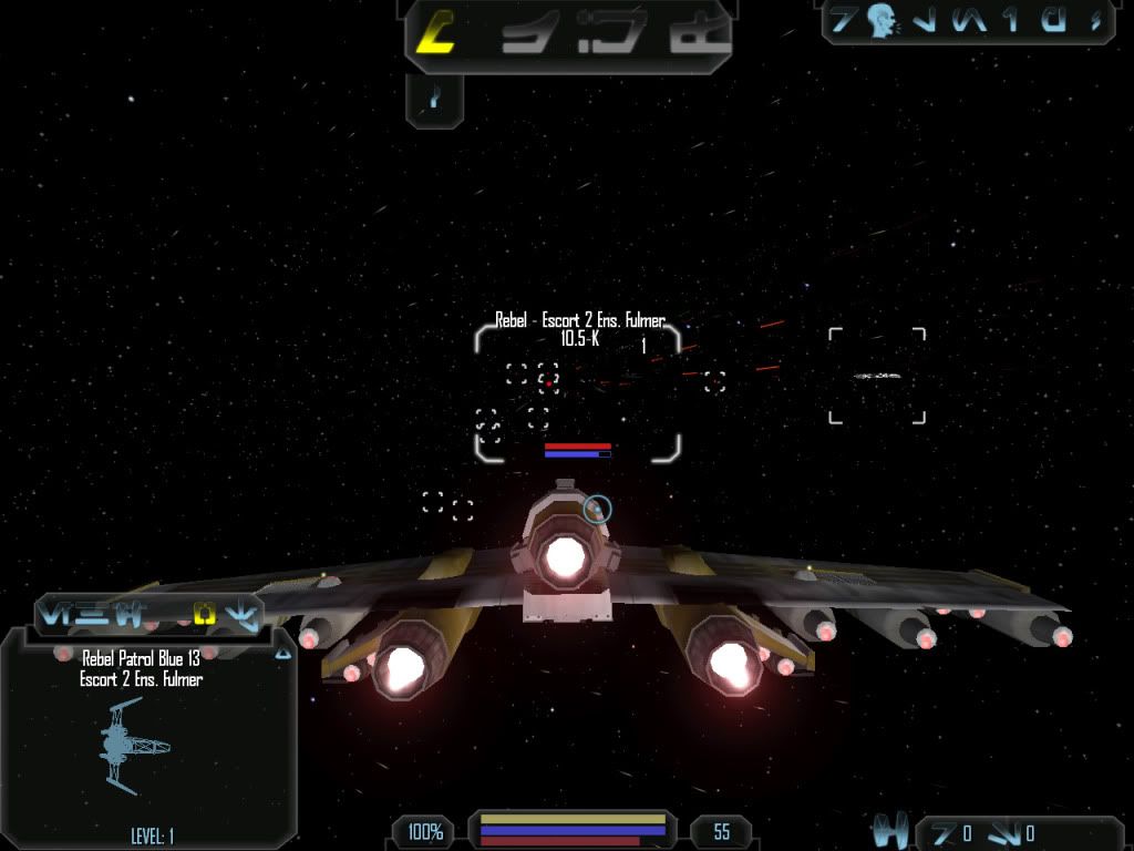
What is very strange is that the fighter sized craft, the ones that range from 7-100m are all perfect:

This is the exact same .cmp, .mat and .sur for both images
So, I tried to do some editing. I changed the radius of the capital ship .cmp to 10m, no change. I changed the .sur radius, no change. I reduced the size of the .cmp and .sur and I get an even smaller wireframe. I then thought maybe it was related to the shiparch, so I change the ship type and class of the capital ships to fighters and still, no change.
So…I’m sorta at a loss right now with no inkling of what to try next. Can any give me some direction or insight?
Thanks fellas.
-
Thanks for the fix, OP. However, I still have a problem of all the hardpoints are still at the 1:1 scale. So, basically, I have this proper sized wireframe on the HUD which is 2:1 scale and the hardpoints which are all clustered way inside the wireframe at 1:1.
If no one comes up with a better solution, I’ll definitely use this method, though.
-
Have you been following the other “cmp to sur” topic? The radius has a scale applied to it, maybe that’s what you need to change. Try using my update to SurFileDump to have a look (still a command line utility, if that bothers you). Of course, I could be totally wrong, too, since the modelling side of things is not something I know.
-
Thanks for the assist here, Adoxa. Sadly that didn’t really reveal anything I could use.
I just wish I knew more how FL reads the vwiredata to reveal the image on the HUD.
-
**Sushi, if you would, send me a link with a download for the model in PM, I will check each part since my CMP Editor allows me to look at just about every type of node…
Please include the cmp, mat and sur.**
-
Using the docking ring (DATA\SOLAR\DOCKABLE\docking_ringx2_lod.cmp) as a test, I had a bit of a play. After spending ages wondering why nothing was happening, I finally double-checked the ID and realised I was using the wrong name. D’oh! So, use utf_edit to export the VWireData and note the VMeshLibID. Use CRCTool to find that reference. Then make sure the vertices in the VMeshData are the same scale as in the library used by the VMeshRef data. For example, in the docking ring, dock1a_lod1’s VWireData MeshID is 0xFDB50A2c. CRCTool shows this to be data.solar.dockable.docking_ringx2_lod.lod1-112.vms. The VMeshRef ID points to the lod0 entry, so the object and its wireframe are actually unrelated.
Well, that’s what happens with that particular model. I guess it’s possible that whatever you’ve used to export has combined the wireframe vertices in with the model itself. If that’s the case, the Unknown value is actually the base vertex. So if Unknown is 0x5a, then v10 points to vertex 0x5a + 10 = 100.
Hope all that makes sense.
-
Thanks for looking into it LS. Here’s a link to the Nebulon-B and the X-Wing for comparison. If you’d like other ships let me know

http://www.filefront.com/15291775/ships.rar
@Adoxa: I’m sorry but I don’t get exactly what you’re saying :$
-
**Try adjusting the z_nebulon-b_1_lod1.3db ‘radius’ size.
; DB Software - CMP Editor Script [VMeshRef] DataSz = 60 VMeshCRCN = 3818775415 StartVtx = 10508 VtxUsed = 20 StIdx = 26829 IdxECnt = 36 MeshNum = 12 MeshCnt = 1 Bounds = 68.9550781250, -68.9500122070, 127.6444396973, -192.8117370605, 298.9129638672, -301.3523254395 Center = 0.0025329590, -32.5836486816, -1.2196807861 Radius = 455.4263000488 <--- here ```** -
I tried adjusting it into four different sizes, 150, 300, 600, 1200 and it didn’t change the size of the wireframe and causes the model to be invisible ingame.
Back to the drawing board

@Adoxa - How did you place the wireframe into the li_fighter.cmp? Or did you just replace the nebulon-b.cmp into the vanilla code? I wonder if it’s a code thing? Which could explain why my fighter sized craft are fine and my capitals are buggered.
Thanks for the help fellas, it’s greatly appreciated!
-
I literally just swapped the files, so nebulon-b.cmp was used instead of li_fighter.cmp. Of course, nothing was visible in space (even after swapping li_playerships.mat), but the wireframe was fine. Changing type to CAPITAL made no difference, but that’s as far as I went. (Actually, I did double all the vertices in the wire VMeshData, but that just made it so big it didn’t fit, which is when I went back to your screens and realised it was the right size in the first place.)
-
Did you swap out the SUR too? It seems like it’d be a code problem… Which is rather peculiar.
-
So does anyone have anymore insight on this or should I settle for just doubling the size of the wireframe and have the hardpoint being to small problem?
-
Turns out it’s not the ship at all, but equipment in the loadout. The TOW\ships\generic\extra.cmp used by the shield and power is the cause of the reduced wireframe. Don’t really know the proper solution, but increasing the radius to 456 (from 6; hexedit at 0x8B9, from C0 40 to E4 43) seemed to work fine (but will probably cause problems for other ships using it).
-
Awesome! Thanks so much, Adoxa. I’ll figure out something

-
Hmm, tried that method and I didn’t receive any result, Adoxa. I even tried increasing the radius of the .sur file with the increased .cmp.
That being said, you were right about the .cmp causing the issue. , Once I removed that extra.cmp, the wireframe was perfect. So now I have to figure out about getting a proper wireframe for the shield and power generators. But I’m sure that’d doable.
Thanks again for all your help on the matter. It will really make the immersion factor of FW:ToW that much more
